Difference between revisions of "Geeetech M1 3D printer"
(→How to Import Profiles into Cura) |
(→How to import configuration files into Orcaslicer) |
||
| (86 intermediate revisions by the same user not shown) | |||
| Line 1: | Line 1: | ||
| + | <big>Special reminder:After you receive the goods, please carefully check whether the X-axis belt is loose | ||
| + | |||
| + | If it is loose, please adjust the X-axis belt before using it. For detailed steps, please refer to: 2.9</big> | ||
| + | |||
==Printer Introduction== | ==Printer Introduction== | ||
| + | |||
GEEETECH M1 printer uses the FDM (Fused Deposition Modeling) principle to slice and convert the 3D model, and then print the finished product layer by layer. | GEEETECH M1 printer uses the FDM (Fused Deposition Modeling) principle to slice and convert the 3D model, and then print the finished product layer by layer. | ||
| − | This printer has a series of innovative designs such as a detachable printing platform, proximity magnetic induction, and WIFI control. It has fast printing speed, high quality of finished products, easy use, simple maintenance | + | This printer has a series of innovative designs such as a detachable printing platform, proximity magnetic induction, and WIFI control. It has fast printing speed, high quality of finished products, easy use, simple maintenance. |
| + | |||
| + | <big>Appearance</big> | ||
| + | |||
| + | [[File:M1_Apperrance_F.jpg]] | ||
| + | [[File:M1_Apperrance_45.jpg]] | ||
| + | |||
<big>Main specifications</big> | <big>Main specifications</big> | ||
| Line 60: | Line 71: | ||
==Printer Maintenance== | ==Printer Maintenance== | ||
| − | === '''How to | + | === '''How to clean the hotend'''=== |
| + | |||
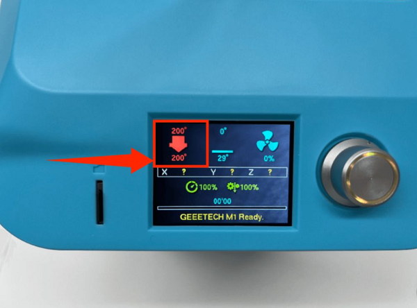
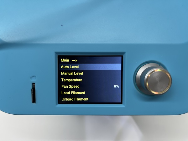
| + | 1. In the menu preheating function, set the nozzle temperature to 200 degrees | ||
| + | |||
| + | [[File:CN_1.png]] | ||
| + | |||
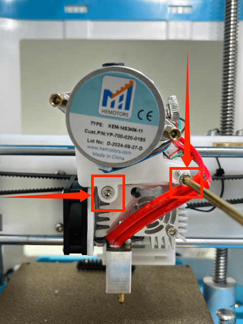
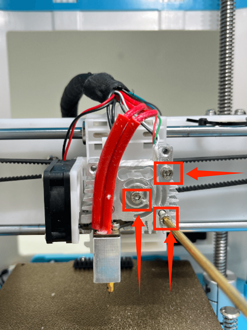
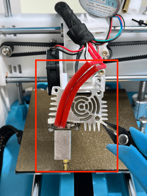
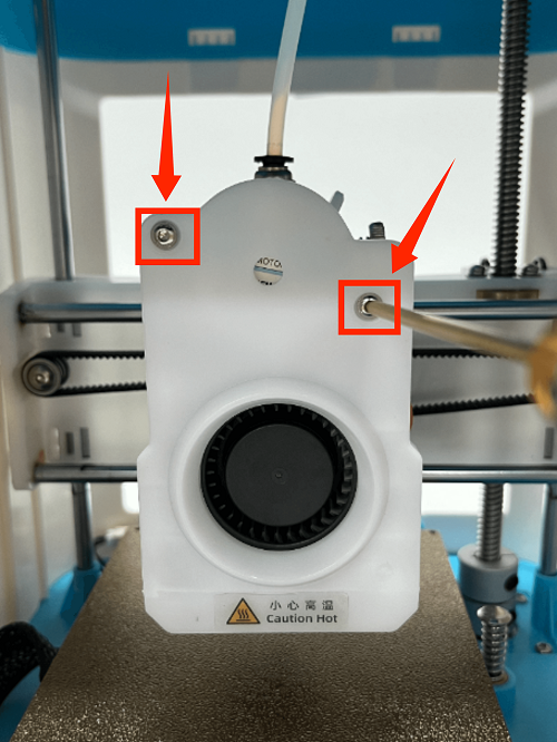
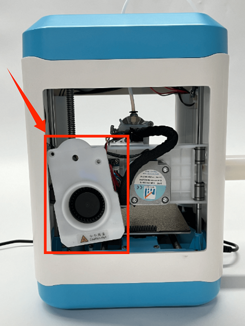
| + | 2. Use an M2 screwdriver to remove the two screws of the print head cover and place it behind (be careful not to tear off the blower fan connection line) | ||
| + | |||
| + | [[File:CN_2.png]] | ||
| + | |||
| + | [[File:CN_3.png]] | ||
| + | |||
| + | 3. First remove the Teflon tube, then insert the cleaning needle from the pneumatic interface (quick plug) until it reaches the bottom, | ||
| + | and squeeze the cleaning needle up and down to squeeze out the consumables | ||
| + | |||
| + | [[File:CN_4.png]] | ||
| + | |||
| + | === '''How to Replace the hotend'''=== | ||
| + | |||
| + | 1. Use an M2 screwdriver to remove the two screws of the print head cover and place it at the back (be careful not to tear off the blower fan cable) | ||
| + | |||
| + | [[File:RHK_1.png]] | ||
| − | === '''How to Replace the | + | [[File:RHK_2.png]] |
| + | |||
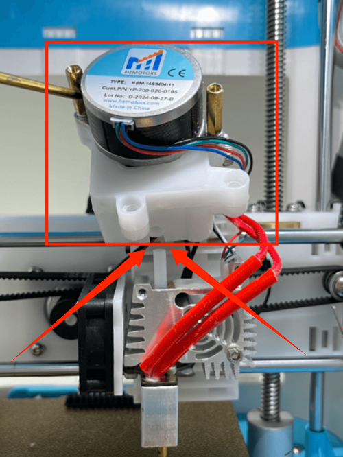
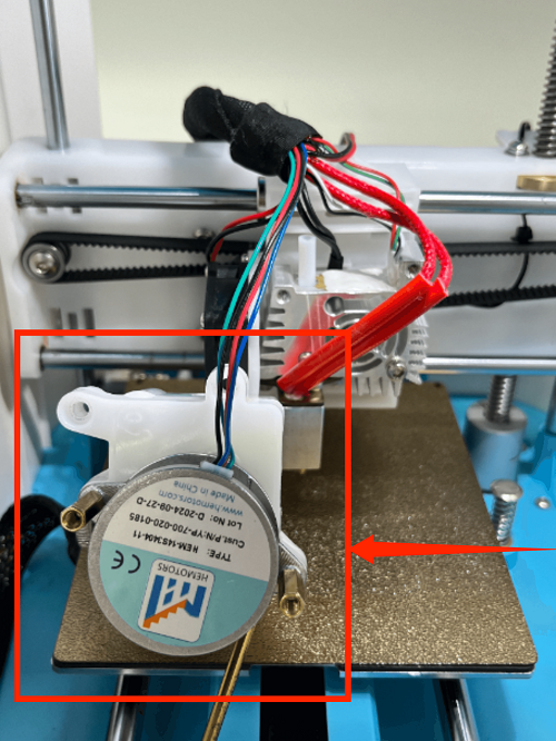
| + | 2. Use an M3 screwdriver to remove the two fixing screws of the extruder assembly and place the extruder assembly at the back | ||
| + | |||
| + | [[File:RHK_3.png]] | ||
| + | |||
| + | 3. Use an M3 screwdriver to remove the three fixing screws of the throat and remove it | ||
| + | |||
| + | [[File:RHK_4.png]] | ||
| + | |||
| + | [[File:RHK_5.png]] | ||
| + | |||
| + | === '''How to replace the nozzle'''=== | ||
| + | |||
| + | 1. In the menu preheating function, set the nozzle temperature to 200 degrees | ||
| + | |||
| + | [[File:RN_1.png]] | ||
| + | |||
| + | 2. Use an M2 screwdriver to remove the two screws of the print head cover and place it behind (be careful not to tear off the blower fan connection line) | ||
| + | |||
| + | [[File:RN_2.png]] | ||
| + | |||
| + | [[File:RN_3.png]] | ||
| + | |||
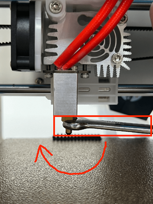
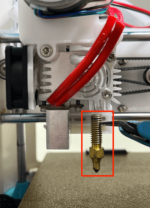
| + | 3. Use the built-in nozzle wrench to remove the nozzle by turning it clockwise | ||
| + | |||
| + | (Please note: the nozzle temperature is very high, do not touch it directly with your hands to avoid burns) | ||
| + | |||
| + | [[File:RN_4.png]] | ||
| + | |||
| + | [[File:RN_5.png]] | ||
| + | |||
| + | 4. Dock the new nozzle in the appropriate position and tighten the nozzle by turning it counterclockwise until it is tightened and not loose | ||
| + | |||
| + | [[File:RN_6.png]] | ||
| + | |||
| + | [[File:RN_7.png]] | ||
| + | |||
| + | [[File:RN_8.png]] | ||
| + | |||
| + | === '''How to Replace the Control Board'''=== | ||
| + | |||
| + | 1. Place the printer upside down | ||
| + | |||
| + | [[File:RM_1.jpg]] | ||
| + | |||
| + | 2. Remove the fan screws on the motherboard and remove the fan | ||
| + | |||
| + | [[File:RM_2.png]] | ||
| + | |||
| + | [[File:RM_3.jpg]] | ||
| + | |||
| + | 3. First remove the connection wire between the motherboard and the print head adapter board, then remove all the connection wires on the motherboard | ||
| + | |||
| + | [[File:RM_4.png]] | ||
| + | |||
| + | [[File:RM_5.jpg]] | ||
| + | |||
| + | 4. Use a screwdriver to remove the 5 fixing screws on the motherboard, unplug the screen button, and remove the old motherboard | ||
| + | |||
| + | [[File:RM_6.png]] | ||
| + | |||
| + | [[File:RM_7.png]] | ||
| + | |||
| + | [[File:RM_8.jpg]] | ||
| + | |||
| + | 5. Place the new motherboard in the right position and fix it with 5 screws | ||
| + | |||
| + | 6. Install the screen connection cable and connect all the cables according to the motherboard wiring diagram | ||
| + | |||
| + | (Please note: do not connect the cables incorrectly) | ||
| + | |||
| + | 7. After installing the motherboard fan, place the printer upright | ||
=== '''How to Replace the Screen'''=== | === '''How to Replace the Screen'''=== | ||
| − | === '''How to Replace the | + | 1. Place the printer upside down |
| + | |||
| + | [[File:RS_1.jpg]] | ||
| + | |||
| + | 2. Remove the fan screws on the mainboard and remove the fan | ||
| + | |||
| + | [[File:RS_2.png]] | ||
| + | |||
| + | [[File:RS_3.jpg]] | ||
| + | |||
| + | 3. First remove the connection wire between the mainboard and the print head adapter board, then remove all the connection wires on the mainboard | ||
| + | |||
| + | [[File:RS_4.png]] | ||
| + | |||
| + | [[File:RS_5.jpg]] | ||
| + | |||
| + | 4. Use a screwdriver to remove the 5 fixing screws on the mainboard, unplug the screen button, and remove the mainboard | ||
| + | |||
| + | [[File:RS_6.png]] | ||
| + | |||
| + | [[File:RS_7.png]] | ||
| + | |||
| + | [[File:RS_8.jpg]] | ||
| + | |||
| + | 5. Unplug the screen connection wire to the left and remove the old display screen | ||
| + | |||
| + | [[File:RS_9.png]] | ||
| + | |||
| + | [[File:RS_10.png]] | ||
| + | |||
| + | 6.Place the new display screen in the right place, install the screen connection cable, and fix it. | ||
| + | |||
| + | 7. Place the new motherboard in the right place and fix it with 5 screws. | ||
| + | |||
| + | 8. Install the screen connection cable and connect all the connection cables according to the motherboard wiring diagram. | ||
| + | |||
| + | (Please note: do not connect the connection cables incorrectly) | ||
| + | |||
| + | 9. After installing the motherboard fan, place the printer upright. | ||
| + | |||
| + | === '''How to Replace the Extruder'''=== | ||
| + | |||
| + | 1. Use an M2 screwdriver to remove the two screws of the print head cover and place it behind (be careful not to tear off the blower fan cable) | ||
| + | |||
| + | [[File:RE_1.png]] | ||
| + | |||
| + | [[File:RE_2.png]] | ||
| + | |||
| + | 2. Use an M3 screwdriver to remove the two fixing screws of the extruder assembly and move the extruder assembly upwards | ||
| + | |||
| + | [[File:RE_3.png]] | ||
| + | |||
| + | [[File:RE_4.png]] | ||
| + | |||
| + | [[File:RE_5.png]] | ||
=== '''How to Automatically Level'''=== | === '''How to Automatically Level'''=== | ||
| + | |||
| + | Note: During the auto leveling process, the nozzle temperature will jump back and forth between 140 degrees and 0 degrees | ||
| + | |||
| + | This is because the system is better adapted to leveling and does not affect the use of auto leveling | ||
| + | |||
| + | 1、In the menu interface, click Prepare first, then click Auto Leveling | ||
| + | |||
| + | [[File:M1_AL_1.jpg]] | ||
| + | |||
| + | 2.The printer will first return to its original position, heat the nozzle hot bed to the preset temperature, | ||
| + | |||
| + | [[File:M1_AL_3.jpg]] | ||
| + | |||
| + | [[File:M1_AL_2.jpg]] | ||
| + | |||
| + | 3、Then the leveling operation will automatically start (no operation is required during this process) | ||
| + | |||
| + | 4、and it will automatically return to its original position after the auto leveling is completed | ||
| + | |||
| + | [[File:M1_AL_4.jpg]] | ||
=== '''How to Manually Level'''=== | === '''How to Manually Level'''=== | ||
| + | |||
| + | 1. In the menu interface, click Prepare first, then click Manual Leveling | ||
| + | |||
| + | [[File:M1_ML_1.jpg]] | ||
| + | |||
| + | 2. After a few seconds, click the button to confirm. | ||
| + | |||
| + | [[File:M1_ML_2.jpg]] | ||
| + | |||
| + | 3. The picture below shows the location of the first leveling point. | ||
| + | |||
| + | However,it can be clearly seen from the picture that the nozzle is too far away from the hot bed, | ||
| + | |||
| + | so we need to adjust the distance between the nozzle and the hot bed by rotating the button. | ||
| + | |||
| + | [[File:M1_ML_3.jpg]] | ||
| + | |||
| + | 4. The best distance between the nozzle and the hot bed is the thickness of an A4 paper | ||
| + | |||
| + | Turn the button counterclockwise to the left to lower the nozzle height and shorten the distance between the nozzle and the hot bed | ||
| + | |||
| + | Turn the button clockwise to the right to raise the nozzle height and increase the distance between the nozzle and the hot bed | ||
| + | |||
| + | [[File:M1_ML_4.jpg]] | ||
| + | |||
| + | 5. There will be a slight friction when pulling A4 paper back and forth. This is the optimal thickness of A4 paper. | ||
| + | |||
| + | [[File:M1_ML_5.jpg]] | ||
| + | |||
| + | 6. Then click the button to enter the next manual leveling point | ||
| + | |||
| + | 7. For other manual leveling points, the same as the first leveling process, | ||
| + | |||
| + | repeat the operation until all manual leveling points are completed, and the manual leveling operation is completed. | ||
| + | |||
| + | [[File:M1_ML_6.jpg]] | ||
| + | |||
| + | === '''How to adjust the X-axis belt'''=== | ||
| + | |||
| + | Please check whether the belt is tight or not. If not, please follow the steps below to adjust it. | ||
| + | |||
| + | [[File:M1_AB_1.png]] | ||
| + | |||
| + | 1. Fix the X-axis motor at the back with your left hand and use a 2.0MM screwdriver to remove the 4 screws of the X-axis motor. | ||
| + | |||
| + | [[File:M1_AB_2.png]] | ||
| + | |||
| + | 2. Fix the X-axis motor with your left hand and adjust the belt tightness by moving the X-axis motor left and right with your right hand. | ||
| + | |||
| + | (Moving the X-axis motor to the left tightens the belt, and moving the X-axis motor to the right loosens the belt.) | ||
| + | |||
| + | [[File:M1_AB_3.jpg]] | ||
| + | |||
| + | [[File:M1_AB_4.png]] | ||
| + | |||
| + | [[File:M1_AB_5.png]] | ||
| + | |||
| + | 3. After adjusting the tightness of the X-axis motor belt, fix the X-axis motor position with your left hand and tighten the 4 screws with your right hand. | ||
| + | |||
| + | [[File:M1_AB_6.png]] | ||
| + | |||
| + | === '''How to remove the upper frame'''=== | ||
| + | |||
| + | 1. First, use the appropriate tool to insert it into the gap | ||
| + | |||
| + | [[File:M1_RF_1.jpeg]] | ||
| + | |||
| + | 2. Hold the white middle frame with your left hand and lift the upper frame with your right hand | ||
| + | |||
| + | [[File:M1_RF_2.jpeg]] | ||
| + | |||
| + | 3. Complete the removal of the upper frame | ||
| + | |||
| + | [[File:M1_RF_3.jpeg]] | ||
| + | |||
| + | === '''Mainboard wiring diagram'''=== | ||
| + | |||
| + | [[File:M1_Motherboard.png]] | ||
| + | |||
| + | [[File:M1_Motherboard_back.png]] | ||
| + | |||
| + | === '''Print head adapter board wiring diagram'''=== | ||
| + | |||
| + | [[File:M1_Adapter_Plate.png]] | ||
==Trouble Shooting== | ==Trouble Shooting== | ||
=== '''Black Screen'''=== | === '''Black Screen'''=== | ||
| + | |||
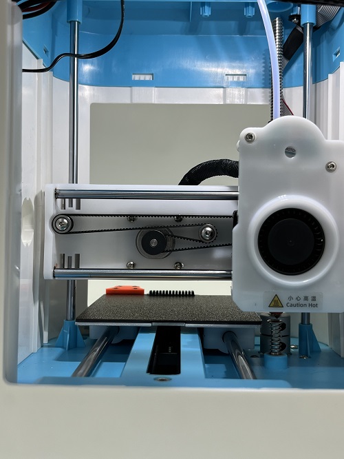
| + | As shown in the figure below, the black screen failure is caused by power supply, display screen, and motherboard failure, which requires further investigation. | ||
| + | |||
| + | [[File:MI_Black_screen.jpg]] | ||
=== ''' Update Firmware'''=== | === ''' Update Firmware'''=== | ||
=== '''Minimum Temperature Error'''=== | === '''Minimum Temperature Error'''=== | ||
| + | |||
| + | As shown in the figure below, a negative temperature fault occurs, which is usually caused by a thermistor. It is recommended that you replug the thermistor connection line and try again. If it still cannot be solved, you need to replace a new thermistor | ||
| + | |||
| + | [[File:M1_temperature_-10.jpeg]] | ||
=== '''Filament cannot be extruded'''=== | === '''Filament cannot be extruded'''=== | ||
| Line 138: | Line 408: | ||
During automatic leveling, the preset temperature will switch back and forth between 140 degrees and 0 degrees, which is normal. | During automatic leveling, the preset temperature will switch back and forth between 140 degrees and 0 degrees, which is normal. | ||
| + | [[File:M1_temperature_0.png]] | ||
| − | [[File: | + | [[File:M1_temperature_140.png]] |
| − | |||
| − | |||
=== '''How to Import Profiles into Cura'''=== | === '''How to Import Profiles into Cura'''=== | ||
First you need to download the Mozi configuration file, then follow the steps below to import the configured Mozi configuration file | First you need to download the Mozi configuration file, then follow the steps below to import the configured Mozi configuration file | ||
| + | |||
| + | [https://www.geeetech.com/download.html?version_id=586 M1 Cura Configuration Files] | ||
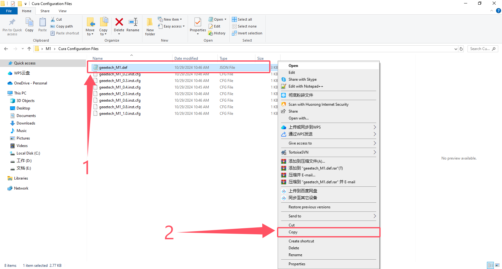
1、 Copy the geeetech M1.def file. Note that you are copying the .Json file. Please do not copy the wrong file. | 1、 Copy the geeetech M1.def file. Note that you are copying the .Json file. Please do not copy the wrong file. | ||
| − | [[File:cura_1.png | + | [[File:cura_1.png]] |
2、 Open the location of the Cura slicing software and copy the geeetech_M1.def.json file to the target path: | 2、 Open the location of the Cura slicing software and copy the geeetech_M1.def.json file to the target path: | ||
| + | |||
\UltiMaker Cura 5.8.1sharecuraresourcesdefinitions | \UltiMaker Cura 5.8.1sharecuraresourcesdefinitions | ||
| − | [[File:cura_2.png | + | [[File:cura_2.png]] |
| + | |||
3、Copy all the configuration files in the picture | 3、Copy all the configuration files in the picture | ||
| − | [[File:cura_3.png | + | [[File:cura_3.png]] |
| − | 4、 Open the location of the Cura slicing software and copy all geeetech_M1.inst.cfg files to the target path: | + | 4、 Open the location of the Cura slicing software and copy all geeetech_M1.inst.cfg files to the target path: |
| − | [[File:cura_4.png | + | \UltiMaker Cura 5.xx\share\cura\resources\variants\geeetech_variants |
| + | |||
| + | [[File:cura_4.png]] | ||
5、 Open the Cura slicing software and follow the steps below | 5、 Open the Cura slicing software and follow the steps below | ||
| − | [[File:cura_5.png | + | [[File:cura_5.png]] |
| − | [[File:cura_6.png | + | [[File:cura_6.png]] |
| − | [[File:cura_7.png | + | [[File:cura_7.png]] |
| − | [[File:cura_8.png | + | [[File:cura_8.png]] |
| − | [[File:cura_9.png | + | [[File:cura_9.png]] |
6、 After the import is successful, select the M1 printer in the printer options and carefully check whether the parameters have been imported successfully. | 6、 After the import is successful, select the M1 printer in the printer options and carefully check whether the parameters have been imported successfully. | ||
| − | [[File:cura_10.png | + | [[File:cura_10.png]] |
=== '''How to import configuration files into Orcaslicer'''=== | === '''How to import configuration files into Orcaslicer'''=== | ||
| + | |||
| + | Special statement:If you update Orcaslicer to V2.2.0, there is a pre-configured M1 printer, which can be directly selected without importing printing parameters. | ||
| + | |||
| + | As shown in the figure below, click Add Printer and search for GEEETECH to find it. | ||
| + | |||
| + | [[File:M1_Orcaslicer_V2.2.png]] | ||
| + | |||
| + | |||
| + | If your Orcaslicer does not have an M1 printer, you need to manually import the slicing parameters. The steps are as follows: | ||
First, you need to download the Mozi configuration file, and then follow the steps below to import the configured Mozi configuration file | First, you need to download the Mozi configuration file, and then follow the steps below to import the configured Mozi configuration file | ||
| + | |||
| + | [https://www.geeetech.com/download.html?version_id=587 M1 Orcaslicer Configuration Files] | ||
1、 Open the Orcaslicer slicing software | 1、 Open the Orcaslicer slicing software | ||
| + | |||
[[File:orcaslicer_1.png]] | [[File:orcaslicer_1.png]] | ||
| Line 200: | Line 487: | ||
3、 Select the downloaded Mozi configuration file and click Open | 3、 Select the downloaded Mozi configuration file and click Open | ||
| + | |||
[[File:orcaslicer_3.png]] | [[File:orcaslicer_3.png]] | ||
4、 Click Yes for all | 4、 Click Yes for all | ||
| + | |||
[[File:orcaslicer_4.png]] | [[File:orcaslicer_4.png]] | ||
5、 A pop-up window will show that the Mozi slicing parameters have been successfully imported | 5、 A pop-up window will show that the Mozi slicing parameters have been successfully imported | ||
| + | |||
[[File:orcaslicer_5.png]] | [[File:orcaslicer_5.png]] | ||
6、 In the printer, select the M1 printer to see if the import is successful | 6、 In the printer, select the M1 printer to see if the import is successful | ||
| + | |||
[[File:orcaslicer_6.png]] | [[File:orcaslicer_6.png]] | ||
| Line 374: | Line 665: | ||
=== '''How to print TPU'''=== | === '''How to print TPU'''=== | ||
| − | Nozzle temperature: 220- | + | Nozzle temperature: 220-240℃ |
Bed temperature: 30-60℃ | Bed temperature: 30-60℃ | ||
Latest revision as of 10:54, 22 November 2024
Special reminder:After you receive the goods, please carefully check whether the X-axis belt is loose
If it is loose, please adjust the X-axis belt before using it. For detailed steps, please refer to: 2.9
Contents
- 1 Printer Introduction
- 2 Printer Maintenance
- 2.1 How to clean the hotend
- 2.2 How to Replace the hotend
- 2.3 How to replace the nozzle
- 2.4 How to Replace the Control Board
- 2.5 How to Replace the Screen
- 2.6 How to Replace the Extruder
- 2.7 How to Automatically Level
- 2.8 How to Manually Level
- 2.9 How to adjust the X-axis belt
- 2.10 How to remove the upper frame
- 2.11 Mainboard wiring diagram
- 2.12 Print head adapter board wiring diagram
- 3 Trouble Shooting
- 3.1 Black Screen
- 3.2 Update Firmware
- 3.3 Minimum Temperature Error
- 3.4 Filament cannot be extruded
- 3.5 Model does not stick to the platform
- 3.6 Print file is not displayed
- 3.7 Abnormal temperature during automatic leveling
- 3.8 How to Import Profiles into Cura
- 3.9 How to import configuration files into Orcaslicer
- 3.10 The consumables don't stick to the hot bed
- 3.11 The print is brushed or leaked
- 3.12 Underextrusion and overextrusion
- 3.13 The top-level seal is insufficient
- 3.14 Print offset
- 3.15 Surface spots and stripes problems
- 3.16 There are gaps between the edge and the filling
- 3.17 Rough edges and corners
- 3.18 Top layer surface scratch problem
- 3.19 Holare holes in the bottom of the corner linet
- 3.20 The side edges are uneven
- 3.21 How to print PLA
- 3.22 How to print TPU
- 3.23 How to print ABS
- 3.24 How to print PETG
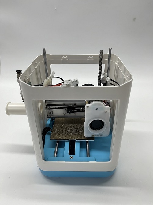
Printer Introduction
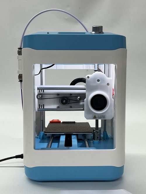
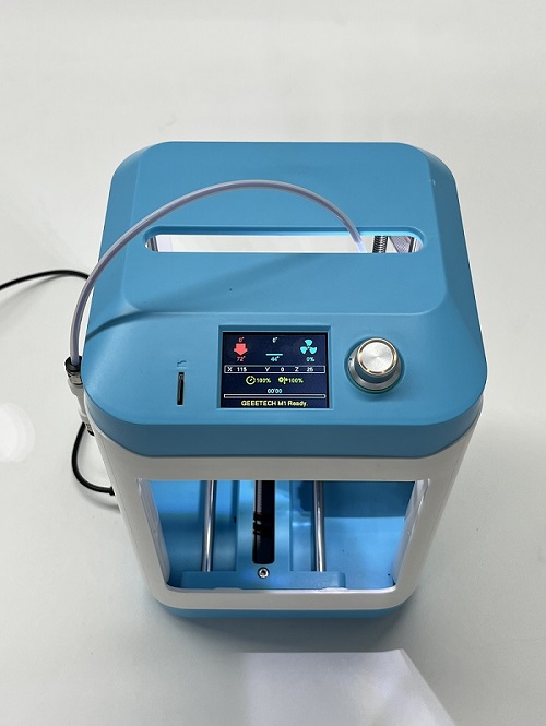
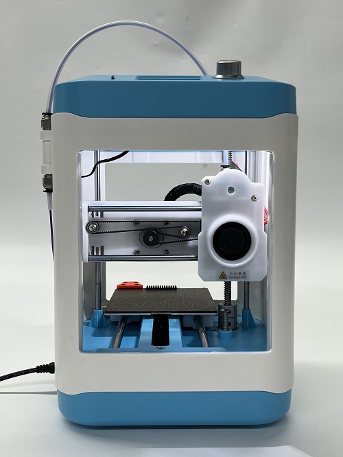
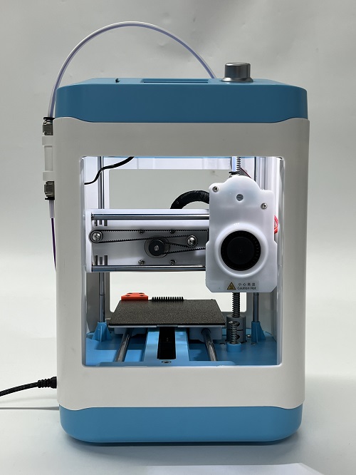
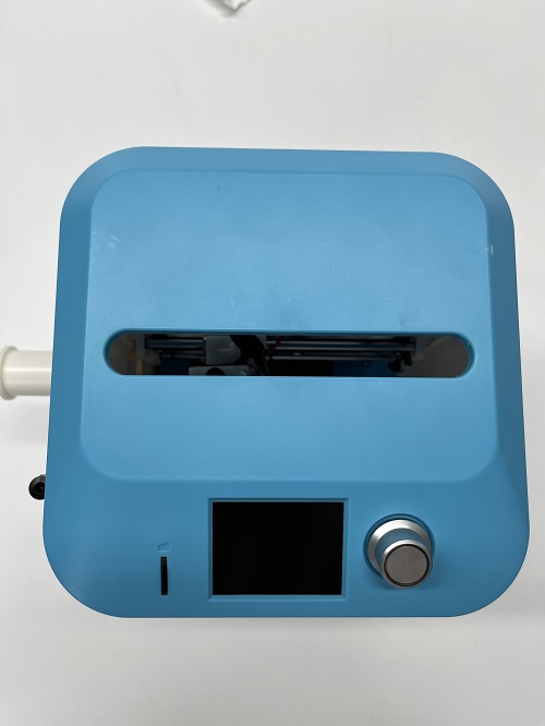
GEEETECH M1 printer uses the FDM (Fused Deposition Modeling) principle to slice and convert the 3D model, and then print the finished product layer by layer. This printer has a series of innovative designs such as a detachable printing platform, proximity magnetic induction, and WIFI control. It has fast printing speed, high quality of finished products, easy use, simple maintenance.
Appearance
Main specifications
Printer type: FDM
Layer thickness: 0.1-0.2 mm
Printing materials: PLA, ABS, TPU, PETG, Silk PLA, Wood polymer
Building platform volume: 100*110*100 mm
Automatic leveling: Yes
Breakpoint resume: Yes
Nozzle diameter: 0.4 mm
Printing accuracy: ±0.1 mm
Printing speed: 10~250 mm/S; 200 mm/s recommended
Operating system: Windows, Mac, Linux,
Slicing software: Cura, Orcaslicer
Supported file formats: .gcode
Highest temperature of hot bed: 60 ℃
Maximum extruder temperature: 230 ℃
Ambient temperature: 10-40 ℃
Electrical Parameter
Power Input:
Power Output: DC 24 V-15 A Max
Connectivity Interface: 1*TF Card, 1*USB cable
Power Supply Unit Certification:
Mechanical Parameter
Net Weight(kg): 3 kg
Gross Weight(kg): 4 kg
Printer Whole Size: 279(W)*200(L)*298(H)mm
Packing Dimension: 257(L)*270(W)*405(H)mm
Watch the unboxing video and user manual before assembling the printer.
Printer Maintenance
How to clean the hotend
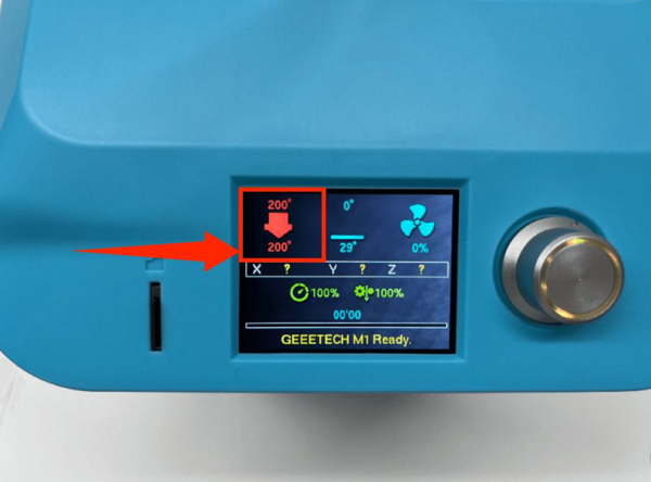
1. In the menu preheating function, set the nozzle temperature to 200 degrees
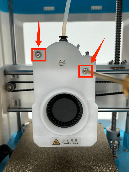
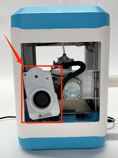
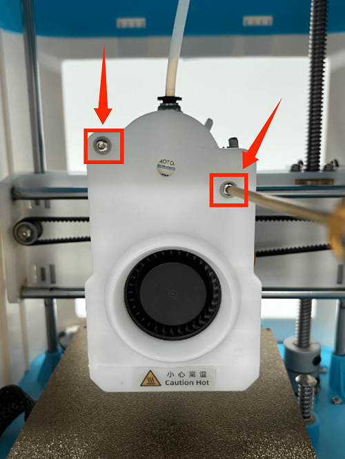
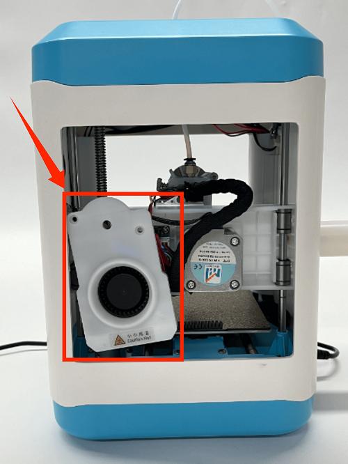
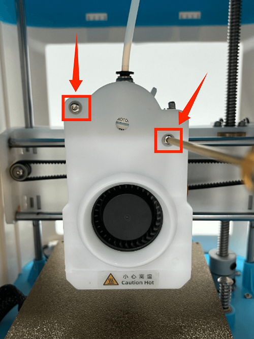
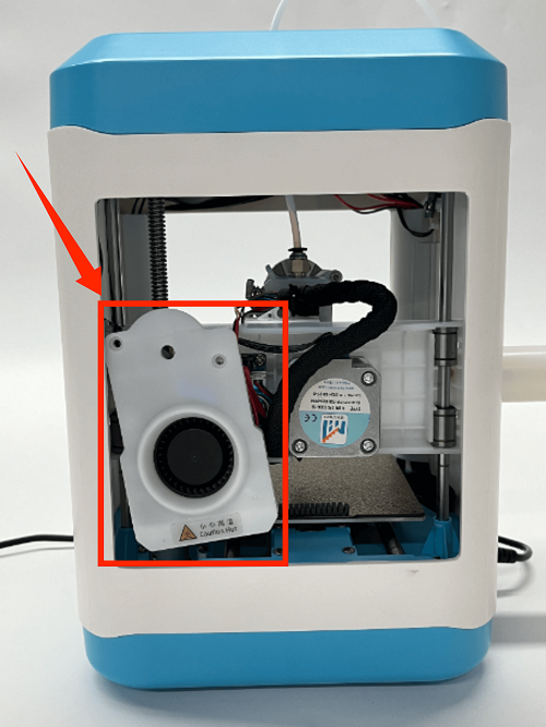
2. Use an M2 screwdriver to remove the two screws of the print head cover and place it behind (be careful not to tear off the blower fan connection line)
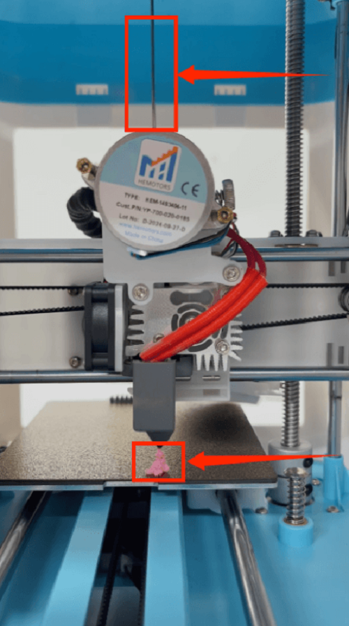
3. First remove the Teflon tube, then insert the cleaning needle from the pneumatic interface (quick plug) until it reaches the bottom, and squeeze the cleaning needle up and down to squeeze out the consumables
How to Replace the hotend
1. Use an M2 screwdriver to remove the two screws of the print head cover and place it at the back (be careful not to tear off the blower fan cable)
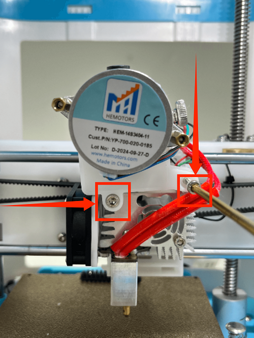
2. Use an M3 screwdriver to remove the two fixing screws of the extruder assembly and place the extruder assembly at the back
3. Use an M3 screwdriver to remove the three fixing screws of the throat and remove it
How to replace the nozzle
1. In the menu preheating function, set the nozzle temperature to 200 degrees
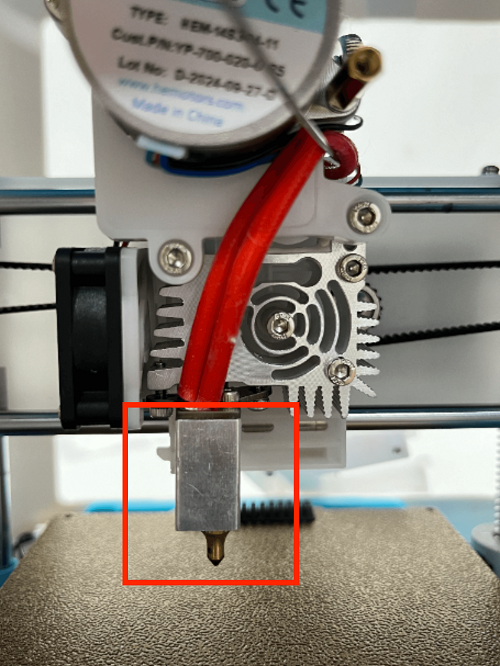
2. Use an M2 screwdriver to remove the two screws of the print head cover and place it behind (be careful not to tear off the blower fan connection line)
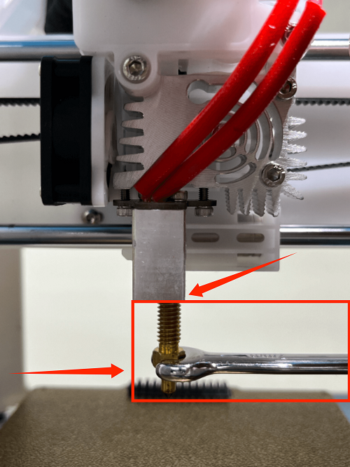
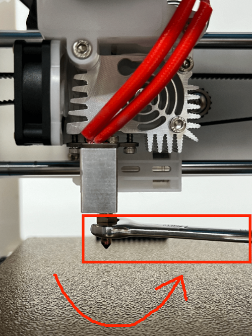
3. Use the built-in nozzle wrench to remove the nozzle by turning it clockwise
(Please note: the nozzle temperature is very high, do not touch it directly with your hands to avoid burns)
4. Dock the new nozzle in the appropriate position and tighten the nozzle by turning it counterclockwise until it is tightened and not loose
How to Replace the Control Board
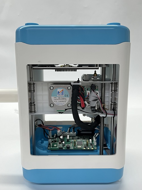
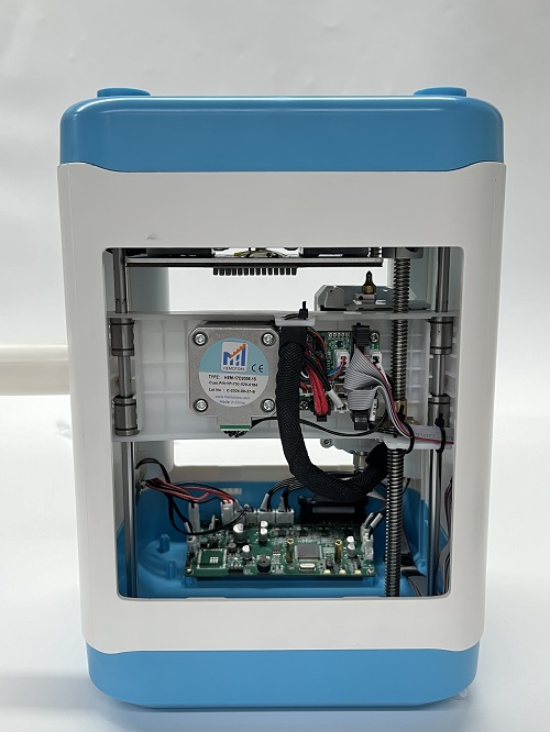
1. Place the printer upside down
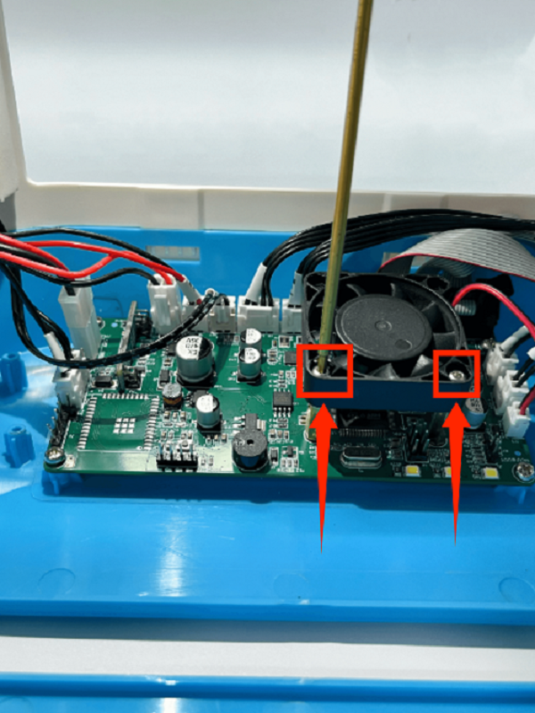
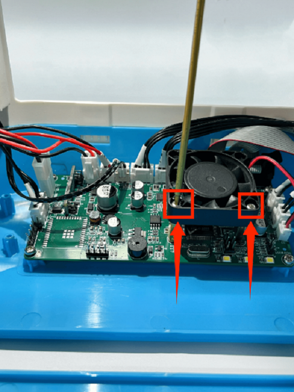
2. Remove the fan screws on the motherboard and remove the fan
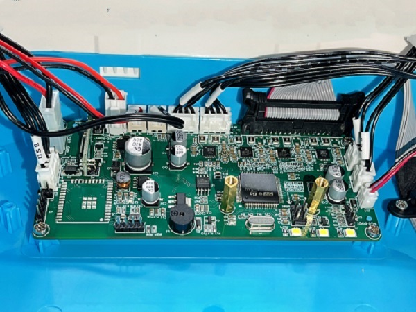
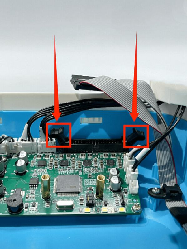
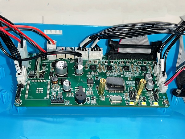
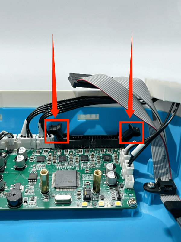
3. First remove the connection wire between the motherboard and the print head adapter board, then remove all the connection wires on the motherboard
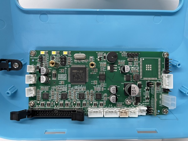
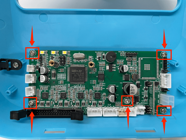
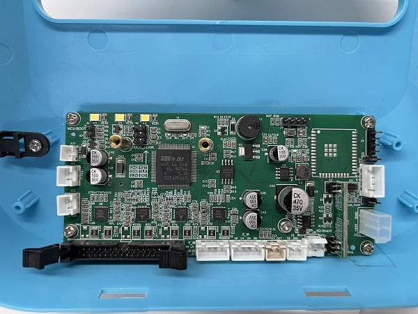
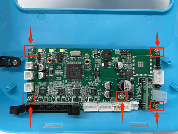
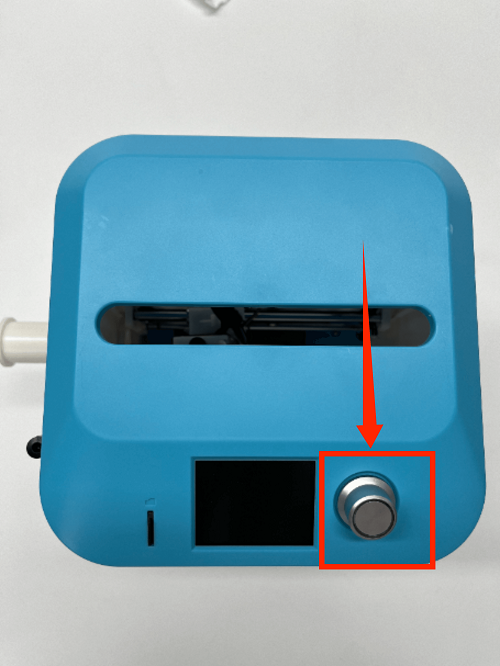
4. Use a screwdriver to remove the 5 fixing screws on the motherboard, unplug the screen button, and remove the old motherboard
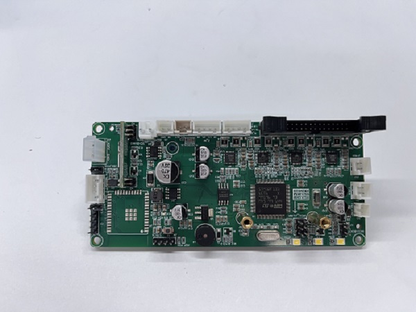
5. Place the new motherboard in the right position and fix it with 5 screws
6. Install the screen connection cable and connect all the cables according to the motherboard wiring diagram
(Please note: do not connect the cables incorrectly)
7. After installing the motherboard fan, place the printer upright
How to Replace the Screen
1. Place the printer upside down
2. Remove the fan screws on the mainboard and remove the fan
3. First remove the connection wire between the mainboard and the print head adapter board, then remove all the connection wires on the mainboard
4. Use a screwdriver to remove the 5 fixing screws on the mainboard, unplug the screen button, and remove the mainboard
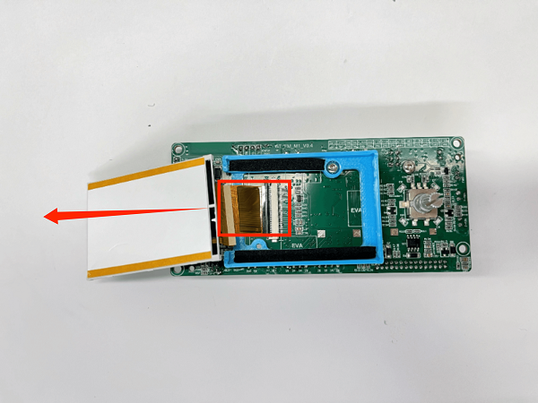
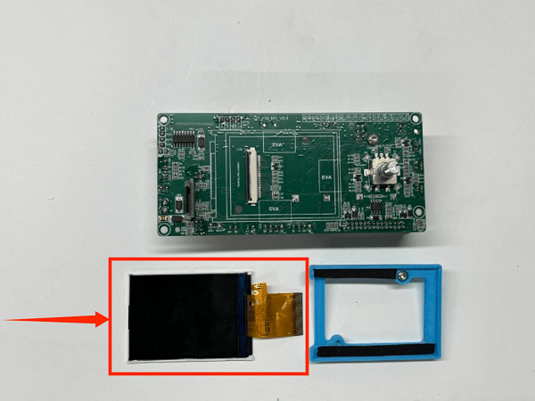
5. Unplug the screen connection wire to the left and remove the old display screen
6.Place the new display screen in the right place, install the screen connection cable, and fix it.
7. Place the new motherboard in the right place and fix it with 5 screws.
8. Install the screen connection cable and connect all the connection cables according to the motherboard wiring diagram.
(Please note: do not connect the connection cables incorrectly)
9. After installing the motherboard fan, place the printer upright.
How to Replace the Extruder
1. Use an M2 screwdriver to remove the two screws of the print head cover and place it behind (be careful not to tear off the blower fan cable)
2. Use an M3 screwdriver to remove the two fixing screws of the extruder assembly and move the extruder assembly upwards
How to Automatically Level
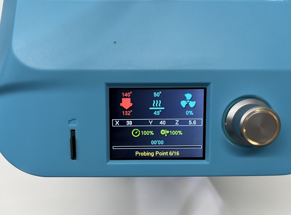
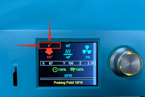
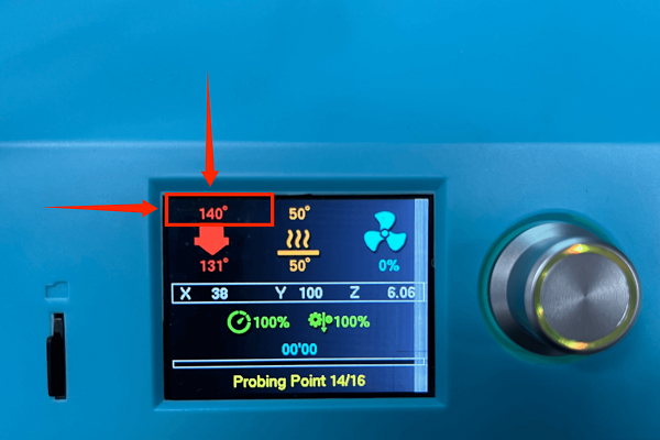
Note: During the auto leveling process, the nozzle temperature will jump back and forth between 140 degrees and 0 degrees
This is because the system is better adapted to leveling and does not affect the use of auto leveling
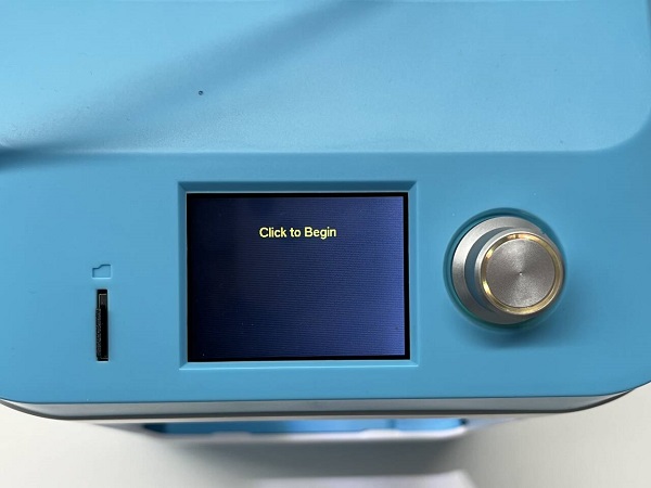
1、In the menu interface, click Prepare first, then click Auto Leveling
2.The printer will first return to its original position, heat the nozzle hot bed to the preset temperature,
3、Then the leveling operation will automatically start (no operation is required during this process)
4、and it will automatically return to its original position after the auto leveling is completed
How to Manually Level
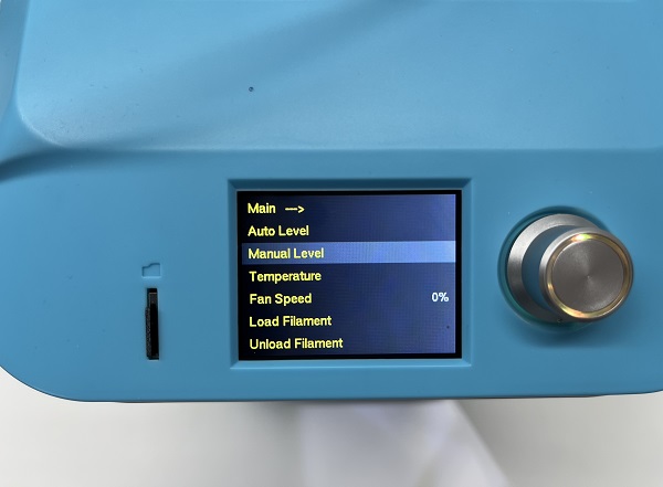
1. In the menu interface, click Prepare first, then click Manual Leveling
2. After a few seconds, click the button to confirm.
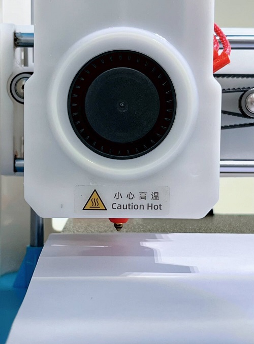
3. The picture below shows the location of the first leveling point.
However,it can be clearly seen from the picture that the nozzle is too far away from the hot bed,
so we need to adjust the distance between the nozzle and the hot bed by rotating the button.
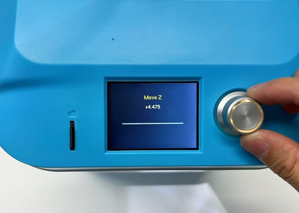
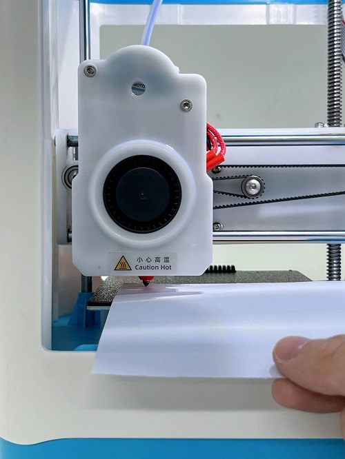
4. The best distance between the nozzle and the hot bed is the thickness of an A4 paper
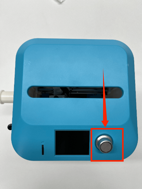
Turn the button counterclockwise to the left to lower the nozzle height and shorten the distance between the nozzle and the hot bed
Turn the button clockwise to the right to raise the nozzle height and increase the distance between the nozzle and the hot bed
5. There will be a slight friction when pulling A4 paper back and forth. This is the optimal thickness of A4 paper.
6. Then click the button to enter the next manual leveling point
7. For other manual leveling points, the same as the first leveling process,
repeat the operation until all manual leveling points are completed, and the manual leveling operation is completed.
How to adjust the X-axis belt
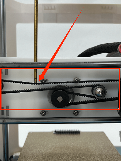
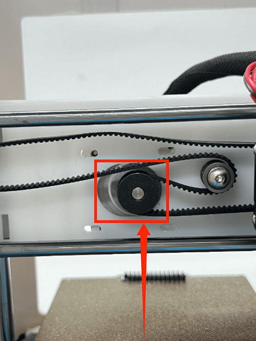
Please check whether the belt is tight or not. If not, please follow the steps below to adjust it.
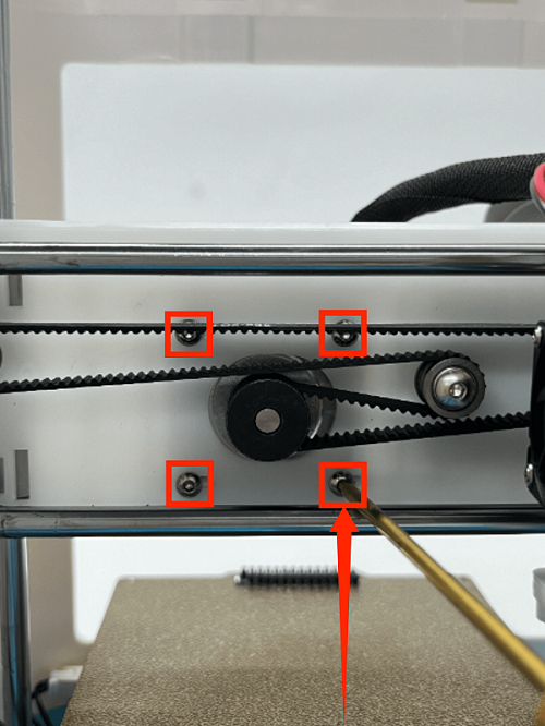
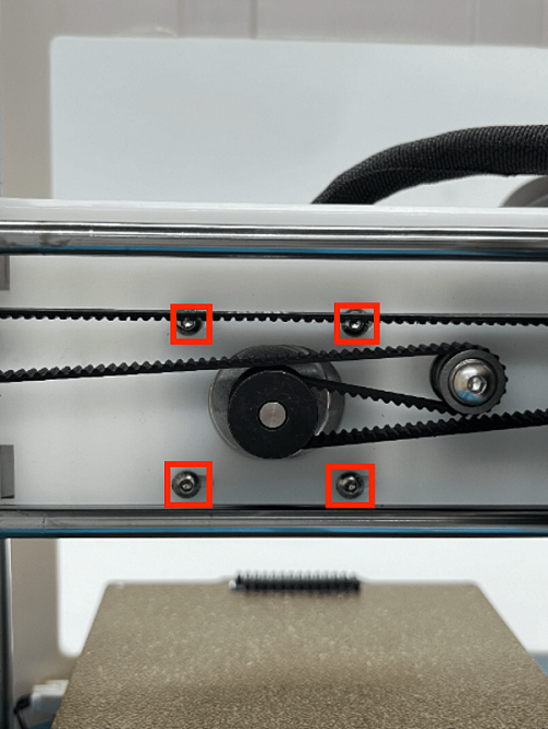
1. Fix the X-axis motor at the back with your left hand and use a 2.0MM screwdriver to remove the 4 screws of the X-axis motor.
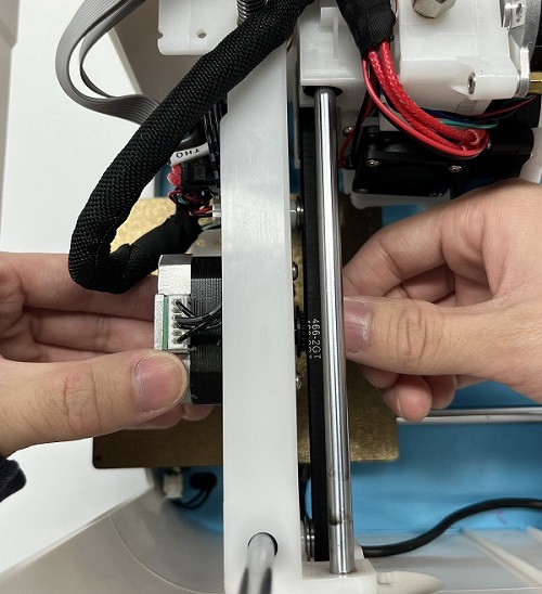
2. Fix the X-axis motor with your left hand and adjust the belt tightness by moving the X-axis motor left and right with your right hand.
(Moving the X-axis motor to the left tightens the belt, and moving the X-axis motor to the right loosens the belt.)
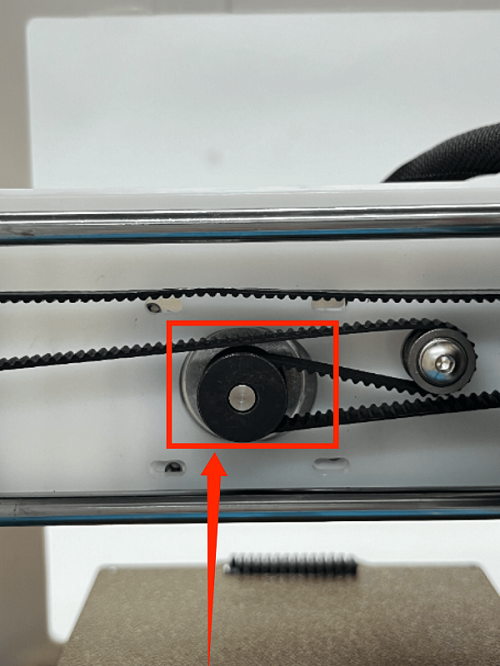
3. After adjusting the tightness of the X-axis motor belt, fix the X-axis motor position with your left hand and tighten the 4 screws with your right hand.
How to remove the upper frame
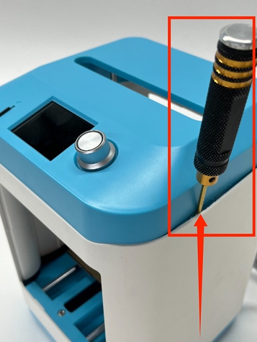
1. First, use the appropriate tool to insert it into the gap
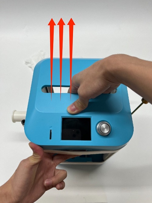
2. Hold the white middle frame with your left hand and lift the upper frame with your right hand
3. Complete the removal of the upper frame
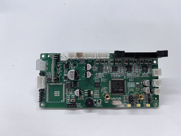
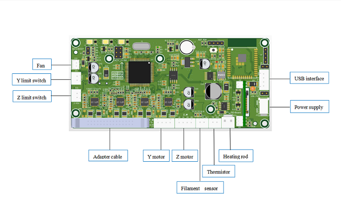
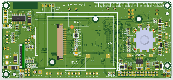
Mainboard wiring diagram
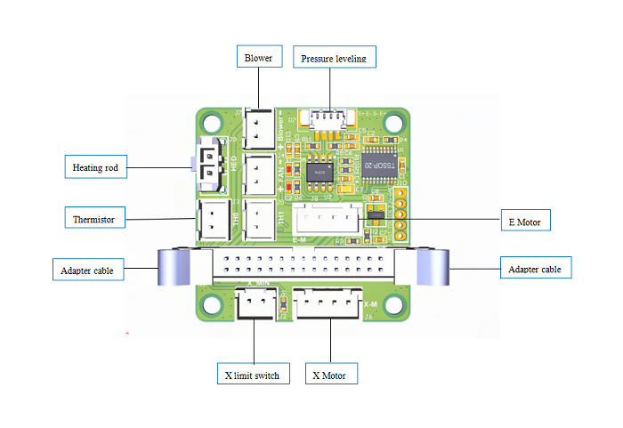
Print head adapter board wiring diagram
Trouble Shooting
Black Screen
As shown in the figure below, the black screen failure is caused by power supply, display screen, and motherboard failure, which requires further investigation.
Update Firmware
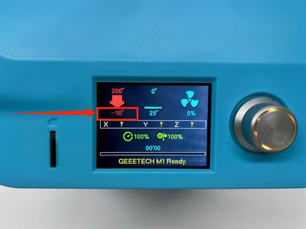
Minimum Temperature Error
As shown in the figure below, a negative temperature fault occurs, which is usually caused by a thermistor. It is recommended that you replug the thermistor connection line and try again. If it still cannot be solved, you need to replace a new thermistor
Filament cannot be extruded
1、 Before printing, the filament is not loaded in place
Solution: Stop printing first, and heat the nozzle temperature to the appropriate temperature. Set the PLA material to 200 degrees, the PETG material to 230 degrees, and the ABS material to 240 degrees, and then feed manually
2、 The nozzle is too close to the platform
Solution: Perform manual leveling or automatic leveling, and readjust the printer platform. It is recommended that the distance between the nozzle and the platform is 0.3mm, which is the thickness of an A4 sheet
3、 The printer is blocked
Solution: Use a needle to clean the nozzle deeply. First, heat the nozzle temperature to between 230 and 250, and pull out the filament when the temperature reaches the set value, and then use our matching needle to insert the small hole of the nozzle from bottom to top to repeatedly dredge it. After cleaning, manually insert the filament until the nozzle flows out of the filament normally.
Model does not stick to the platform
1、 The nozzle is too far from the platform
Solution:Adjust the Z-axis compensation value through automatic leveling or automatic leveling. The distance from the nozzle to the platform is about the thickness of an A4 paper
2、 The first layer is printed too fast
Solution:The printing speed can be reduced to ensure that the first layer is well bonded to the platform. You can reduce the printing speed by adjusting the knob on the screen, or set the first layer printing speed in the slicing software, preferably in units of 10%
3、 Add Birm in the slicing parameters
Solution:Adding inner and outer Brim can increase the contact area of the model, ensure that the model is better attached to the hot bed, and also ensure that the model is not easy to fall off during printing
4、 There is a problem with the temperature or cooling setting:
Solution:
(1) Temperature setting: PLA sets the nozzle temperature to 190-210 degrees and the hot bed temperature to 50-60 degrees. The temperature of the ABS nozzle is 240 degrees, and the temperature of the hot bed is 70~100. (2) Fan setting: When using ABS filaments, the fan does not need to be turned on during the entire printing process. When using PLA filaments, the fan needs to be turned on 100%
5、 Platform surface treatment (tape, glue)
Solution: Replace the Jietai Mylar sheet, apply masking tape or apply solid glue. If there is damage and it cannot be adhered, please replace the Mylar sheet. At the same time, different filaments have different adhesion to different materials. You can use white masking tape or solid glue. PVP solid glue can be evenly applied on the platform.
Print file is not displayed
First of all, the slice file must be in .gcode format . The printer cannot recognize other formats
Please format the TF card first and download the test file from the official website,link here
1、Save the downloaded .gcode file to the TF card, then insert the TF card into the printer to see if the slice file can be displayed normally
2、 If the slice file cannot be displayed, please replace the new TF card and try again. If the new TF card can be displayed normally, it is the fault of the old TF
3、 If the slice file still does not display after trying multiple TF cards, it is the TF card driver on the motherboard. You need to replace it with a new one
Abnormal temperature during automatic leveling
During automatic leveling, the preset temperature will switch back and forth between 140 degrees and 0 degrees, which is normal.
How to Import Profiles into Cura
First you need to download the Mozi configuration file, then follow the steps below to import the configured Mozi configuration file
1、 Copy the geeetech M1.def file. Note that you are copying the .Json file. Please do not copy the wrong file.
2、 Open the location of the Cura slicing software and copy the geeetech_M1.def.json file to the target path:
\UltiMaker Cura 5.8.1sharecuraresourcesdefinitions
3、Copy all the configuration files in the picture
4、 Open the location of the Cura slicing software and copy all geeetech_M1.inst.cfg files to the target path:
\UltiMaker Cura 5.xx\share\cura\resources\variants\geeetech_variants
5、 Open the Cura slicing software and follow the steps below
6、 After the import is successful, select the M1 printer in the printer options and carefully check whether the parameters have been imported successfully.
How to import configuration files into Orcaslicer
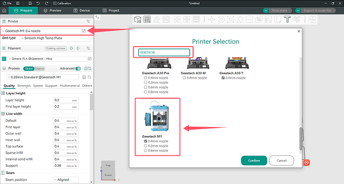
Special statement:If you update Orcaslicer to V2.2.0, there is a pre-configured M1 printer, which can be directly selected without importing printing parameters.
As shown in the figure below, click Add Printer and search for GEEETECH to find it.
If your Orcaslicer does not have an M1 printer, you need to manually import the slicing parameters. The steps are as follows:
First, you need to download the Mozi configuration file, and then follow the steps below to import the configured Mozi configuration file
M1 Orcaslicer Configuration Files
1、 Open the Orcaslicer slicing software
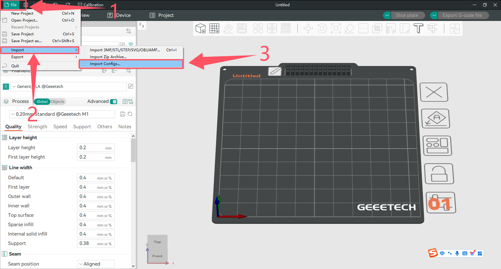
2、 (1) Click File in the upper left corner
(2) Click Import
(3) Click Import Configs...
3、 Select the downloaded Mozi configuration file and click Open
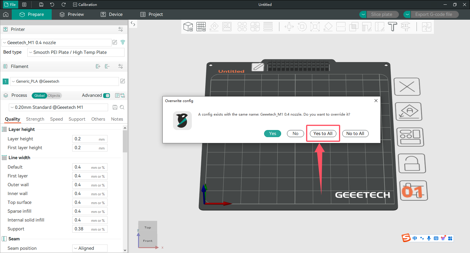
4、 Click Yes for all
5、 A pop-up window will show that the Mozi slicing parameters have been successfully imported
6、 In the printer, select the M1 printer to see if the import is successful
7. Note: Orcaslicer can only import one configuration file at a time. If you need to import other nozzle configuration files, just follow the above steps and import them one by one.
The consumables don't stick to the hot bed
1.Nozzle is too close to the hotbed
Even though the extruder is working but no filament is depositing on the hotbed, Check if the nozzle is too close to the hotbed. Adjust the Z-offset value slightly will help.
2.Print temperature is too low
Some filament needs more higher temperature, manually feed the filament, if it can not be extruded, please try increase the print temperature.
3.The extruder is not working
Check if the grub screw on the extruder gear. If the grub screw is loose, the gear will fail to grab the filament when feeding into the hotend. Also check if the extruder motor is connected properly.
The print is brushed or leaked
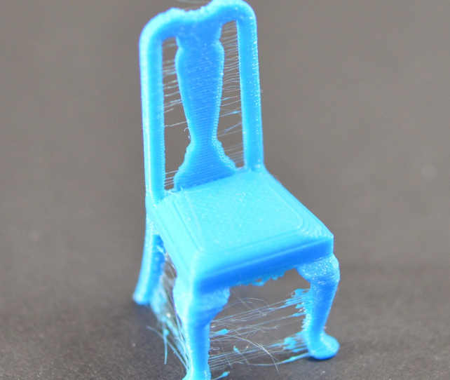
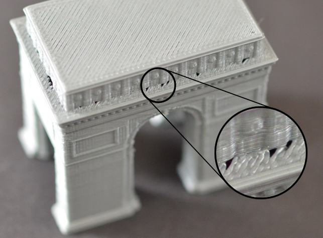
The drawing is the residual linear object left when the extruder crosses the open space. The common measure to solve this problem is to control the "withdrawal" function in the slice software. If the tap is opened in the slice, the consumables will be pulled back in the opposite direction for a distance before the sprinkler head is moved to the next point. When the product moves to the next point, the consumables will be squeezed out again. Although theoretically, it can be avoided, there are several problems in practice:
1. Insufficient withdrawal distance The most important setting in the return is the return distance, which determines how much plastic is drawn from the nozzle during the return. Usually, the more plastic the draw from the nozzle, the less obvious the drawing is.
2. The withdrawal speed is too slow Another important setting in the withdrawal is the speed of the withdrawal, which determines how fast the consumables are withdrawn. If the pump rate is too slow, the melted supplies will still flow out of the nozzle. If the withdrawal is too fast, the separation of the unmelted part and the melted part of the consumables may occur, or the extrusion wheel may bite off a piece of the consumables.
3. The temperature is too high If the temperature of the extrusion head is too high, the consumables in the nozzle will become very sticky, and it is easy to flow out of the nozzle, but if the temperature is too low, the consumables are more difficult to squeeze out. In the determination of the drawing distance and drawing speed are more appropriate, there is still a drawing situation, you can try to reduce the temperature of the extrusion head by 5-10 degrees Celsius.
4, the suspended movement distance is too long The suspended distance will also have a great impact on the drawing. The short distance movement, the melted consumables do not have enough time to flow out of the nozzle, but the long distance movement is very easy to produce the phenomenon of drawing. Some slicing software has relevant Settings, which can avoid the long distance movement.
Underextrusion and overextrusion
For most 3D printers, how much material the extruder squee. In the process of printing, due to some problems, the extrusion of the material will be less than expected. This requires the user to carefully look at the printed work to see if there are irregular distances between the textures and, and if so, usually for the following reasons.
1.Material diameter When users buy materials, it is usually recommended to buy formal brand products. When buying inferior products, the diameter of the material may be unequal. For such materials, the diameter can usually be tested with measuring calipers to ensure that the diameter of the material is consistent with the package label.
2.Increase extrusion multiple If the material diameter and identification is maintained, but there is a lack of extrusion material, then the extrusion speed needs to be adjusted. This is a very practical setting for the user, who can directly modify the amount of extrusion to squeeze more material. ABS material usually presses 109%, while PLA is 105%.
3.Reduce extrusion speed If the material is normal and the extrusion is too much, the extrusion is reduced to keep the printing at a normal level.
The top-level seal is insufficient
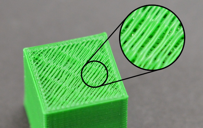
In order to save printing materials, most 3D printers will use different filling methods for the internal space, the commonly used ratio is 20% -30%, that is to say, in the closed product interior, only 20% -30% of the material, in this case, the work can still maintain a certain strength. However, in some of the works, users will find that some of the works are not perfect, and even have holes or gaps. If you encounter this problem, here are a few simple Settings, you can adjust and fix it.
1. Top layers When the number of capped layers is insufficient, it is easy to lead to the phenomenon of material falling, and the number of layers can be increased accordingly;
2. The filling rate is too low Too much reduction of the filling material, will make the internal space is too large, resulting in the number of upper layers can not be effectively supported, it is suggested to increase the internal filling ratio;
3. Insufficient extruding materials of the extruder Due to the lack of extrusion material, the nozzle can not meet the expected requirements, which can be adjusted by adjusting the extrusion amount.
Print offset
Most printers use a stepper motor to drive the machine in motion, meaning that the printer has no function to detect where the print head is located. However, once the stepper motor receives external force interference, or there is a large resistance, it may lead to the printing head dislocation, and the printer does not detect and correct the measures, so that the printed product produces dislocation \ displacement and other conditions.
1. The print head moves too fast If the printing speed or empty speed exceeds the speed the stepper motor can handle, dislocation will occur. Adjust the low walking speed, and lower the acceleration if necessary.
2. Mechanical or electronic reasons If the above does not solve your problem, then you need to check the mechanical and electronic aspects, most machines use belt drive, over time, the belt may lengthen and become loose, thus causing the belt to slip from the pulley. The solution is also relatively simple, the belt drive mechanism will generally have to adjust the tension degree of the belt mechanism, the belt adjustment is more tight some can be solved. However, it should be noted that if the adjustment is too tight, it will form a huge resistance between the rotating shaft and the bearing or may be unable to rotate. So the degree of tightness needs to be moderate. Another mechanical problem is the machine meter screw (top wire), this small screw is used to fix the pulley on the stepping motor shaft, so that the pulley rotates with the motor shaft, but if the screw is loose, there will be shaft rotation and the wheel will not turn. This situation also causes the problem of layer offset. The electronic problem may be that the stepper motor power supply current is insufficient, resulting in the stepper motor is not enough force to overcome the resistance. It may also be that the stepper motor drives the chip to overheating, causing the stepper motor to stop turning before the chip is cooled. There are many other points in electronics.
Surface spots and stripes problems
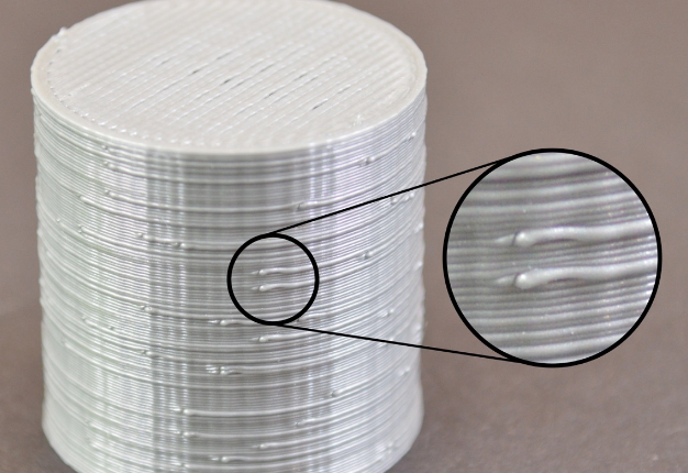
In the process of 3D printing, the extruder frequently extracts, most of the extruder can maintain a good extrusion width in the movement, however, in each withdrawal and extrusion process, there will be additional vibration. For example, if you look closely at the outer surface of the printed object, you may be able to see very small traces, the place where the printing begins. 3D printing starts at certain locations on the outer edge, and eventually goes back to the starting place. The trace is usually represented by surface spots or stripes; several ways to improve the problem:
1. Return extraction and slide wipe setting If you find such traces on the surface of the printed piece, you can first observe the printing process at the beginning of each layer? Or do they appear after each layer is printed? If it appears before starting printing, the value of "restart additional extrusion distance" in the slicing software should be modified to be negative; if the withdrawal distance is 1.00mm and the additional extrusion distance is-0.2mm, the withdrawal is 1.00mm, but only 0.8mm. This should improve the problem of developing traces before starting printing. If this appear after the end of each layer, you need to adjust another setting called "taxi wipe", which causes the extruder to stop extrusion near the end, release the pressure, and the taxiway end point. This value was adjusted until the trace disappeared. In general, this value is set to 0.2-0.5mm.
2. Avoid unnecessary withdrawal In general, in the slicing software, there will be the option of "withdrawing only when crossing the open area". After this option is opened, the 3D printer will not turn on the withdrawal when crossing the internal space of the object. This can reduce the occurrence of traces, in addition to the bowden extruder, and the extruder far from the nozzle, close the back may perform better;
3. Non-fixed point backwithdrawal The conventional withdrawal will pause during the withdrawal, which is not suitable for the extruder with high internal pressure during bowden printing. Some slicing software can set the "wipe nozzle" option, which will cause the printer to continue to move during the withdrawal. In general, the wipe distance is set to 5mm;
4. Set the printing start point All slicing software provides the option to print the starting point, which can start printing at a location specified by the user. For example, in a building, you can set the starting point on the back side of it, so that when printing, these traces will be arranged on the back side of the building, and these points are not visible on the front side.
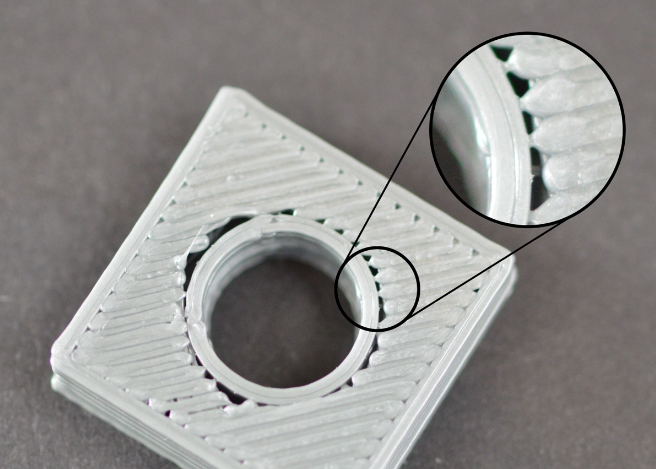
There are gaps between the edge and the filling
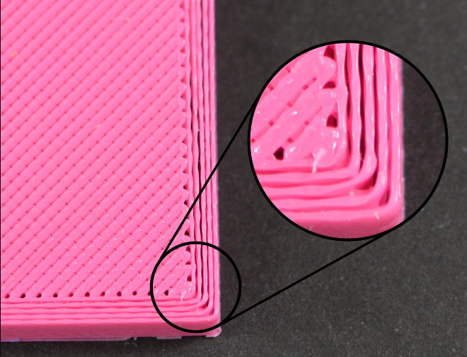
1. Insufficient edge overlap (overlap) Edge overlap refers to how much the fill overlaps with the internal edge. If you have 20%, try to 30% or more
2. Printing speed is too fast Usually, the fill is much faster than the edges. Too fast filling speed, will let the filling and edge are not enough time to combine. If you change the overlap and the problem isn't solved, try to reduce the printing speed to 50%. If the problem is solved, you can slowly increase the speed until you find the most suitable printing speed for your printer.
Rough edges and corners
This problem is mainly caused by the heat dissipation is not fast enough. After the high temperature supplies are extruded from the nozzle, they will change their shape in the process of slow cooling. If this problem occurs in the very beginning of the printing, you can refer to the "first layer off-platform problem" mentioned earlier
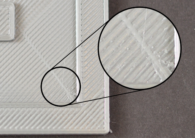
Top layer surface scratch problem
1. Too much plastic extrusion Encounter the problem of scratches, the first thing to check is, is too much consumables extrusion. If the supplies are squeezed out, each layer is thicker than the set size, which means the scratches form when the nozzle moves through. The solution to this problem can refer to the aforementioned "more consumables"
2. Vertical lifting If you are sure your consumables quantity is correct, but still scratch problems, so you can open in slice software "vertical lift" option, this option will make the machine in back, print head up a certain distance, and then move to the next coordinates, then move down back to the original height, continue to print. It's important to note that the print head will be raised vertically only in places where there is a tap. If you want to make sure that each pass has a vertical lift, make sure that the "draw only when crossing open space" and "minimum distance" options are closed.
Holare holes in the bottom of the corner linet
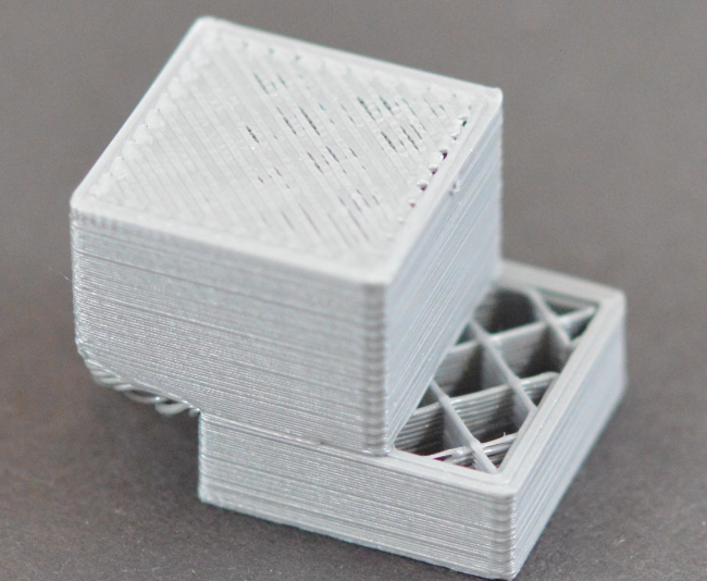
This problem often occurs in the situation where the upper level is smaller than the lower level. The following provides several possible causes and solutions to this problem: 1. Insufficient number of edges You can try increasing the number of edges by two; 2. The number of top layers is insufficient You can try to add the top layers by two layers; 3. The filling ratio is too low You can try to increase the fill ratio by 20%.
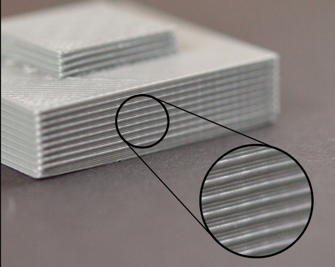
The side edges are uneven
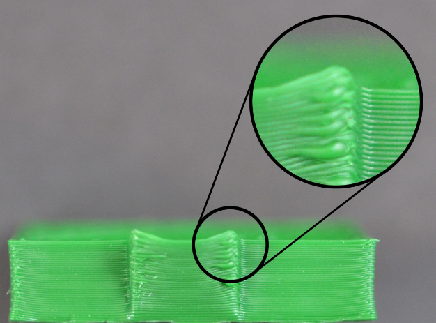
The side of a printed piece is like a thousand-layer cake. In all normal cases, the side of the printed object should look like a smooth surface. Instead of showing the obvious edges, the following are several possible causes and suggested solutions:
1. The extrusion volume is inconsistent Usually this reason is because the tolerance control of the mass line diameter of consumables is not strict. If the line diameter change of your consumables is about 5%, then the extrusion volume change of consumables is as much as 0.05mm. Of course, there are some other possibilities for the inconsistent extrusion quantity, which will be explained in detail in the following "inconsistent extrusion quantity"
2. Temperature change Most 3D printers use PID to control the printing temperature. If the PID setting is not good, the printing temperature will fluctuate up and down (when the temperature rises, the liquidity of consumables is better than when the temperature is low), and the printing temperature fluctuation will affect the extrusion volume. Then, the problem of uneven side edge is generated. A fixed PID control can maintain the printing temperature within 2℃ up and down. If this range is exceeded, the PID needs to be rearranged.
3. Mechanical reasons If you can be sure it's not either, it's probably mechanical. For example, when printing, the printing platform shaking and vibration may lead to the position change of the nozzle, which will lead to inconsistent layer thickness, and thus produce the problem of uneven side edges. Another example: mechanical position or motor differential control problem. Even the small offset of the printing platform can affect each layer of the printed object.
How to print PLA
Nozzle temperature: 190-210℃
Bed temperature: 30-60℃
Fan Cooling: 100%
How to print TPU
Nozzle temperature: 220-240℃
Bed temperature: 30-60℃
Fan Cooling: 100%
How to print ABS
Nozzle temperature: 230-250℃
Bed temperature: 90-110℃
Fan Cooling: 0%
How to print PETG
Nozzle temperature: 220-250℃
Bed temperature: 70-80℃
Fan Cooling: 30%
