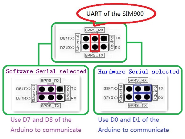
The shield works fine with hardware mode (PIN 0,1) but i can't put working with software mode (7/8).
I put the jumpers the right way and doen't works:

Code: Select all
#include <SoftwareSerial.h>
#include <String.h>
SoftwareSerial mySerial(7, 8);
void setup()
{
 mySerial.begin(19200);  // the GPRS baud rate
 powerUp();
 delay(5000);
 sendSms();
 delay(10000);
}

void powerUp()
{
 pinMode(9, OUTPUT);
 digitalWrite(9,LOW);
 delay(1000);
 digitalWrite(9,HIGH);
 delay(2000);
 digitalWrite(9,LOW);
 delay(3000);
}

///SendTextMessage()
///this function is to send a sms message
void sendSms()
{
 mySerial.print("\r");
 mySerial.print("AT+CMGF=1\r");
 delay(1000);
 mySerial.print("AT+CMGS=\"+34123456789\"\r");
 delay(1000);
 mySerial.print("Arduino SMS Test by soft! \r");//the content of the message
 delay(1000);
 mySerial.print((char)26);//the ASCII code of the ctrl+z is 26
 mySerial.print("\r");
 //mySerial.write(0x1A);
 delay(1000);
}

void loop()
{
}
Code: Select all
void setup()
{
  Serial.begin(19200);  //Baud rate of the GSM/GPRS Module
  powerUp();
  Serial.print("\r");
  delay(1000);
  Serial.print("AT+CMGF=1\r");
  delay(1000);
  Serial.print("AT+CMGS=\"+34123456789\"\r");    //Number to which you want to send the sms
  delay(1000);
  Serial.print("Arduino SMS hard Test! \r");   //The text of the message to be sent
  delay(1000);
  //Serial.write(0x1A);
  Serial.print((char)26);//the ASCII code of the ctrl+z is 26
  Serial.print("\r");
  delay(1000);
}

void powerUp()
{
 pinMode(9, OUTPUT);
 digitalWrite(9,LOW);
 delay(1000);
 digitalWrite(9,HIGH);
 delay(2000);
 digitalWrite(9,LOW);
 delay(3000);
}

void loop()
{
}
[code]

The Shield power up with both code.

Watching this wiki:
[url]http://www.geeetech.com/wiki/index.php/Arduino_GPRS_Shield[/url]

i try with this code to work with hyperterminal/minicom:

[code]
//Serial Relay - Arduino will patch a
//serial link between the computer and the GPRS Shield
//at 19200 bps 8-N-1
//Computer is connected to Hardware UART
//GPRS Shield is connected to the Software UART
#include <SoftwareSerial.h>
SoftwareSerial GPRS(7, 8);
unsigned char buffer[64]; // buffer array for data recieve over serial port
int count=0;     // counter for buffer array
void setup()
{
 GPRS.begin(19200);               // the GPRS baud rate
 Serial.begin(19200);             // the Serial port of Arduino baud rate.
}
void loop()
{
 if (GPRS.available())              // if date is comming from softwareserial port ==> data is comming from gprs shield
 {
   while(GPRS.available())          // reading data into char array
   {
     buffer[count++]=GPRS.read();     // writing data into array
     if(count == 64)break;
 }
   Serial.write(buffer,count);            // if no data transmission ends, write buffer to hardware serial port
   clearBufferArray();              // call clearBufferArray function to clear the storaged data from the array
   count = 0;                       // set counter of while loop to zero
 }
 if (Serial.available())            // if data is available on hardwareserial port ==> data is comming from PC or notebook
   GPRS.write(Serial.read());       // write it to the GPRS shield
}
void clearBufferArray()              // function to clear buffer array
{
 for (int i=0; i<count;i++)
   { buffer[i]=NULL;}                  // clear all index of array with command NULL
}
Code: Select all
sketch_nov19a.ino: In function ‘void loop()’:
sketch_nov19a:17: error: ‘class SoftwareSerial’ has no member named ‘available’
sketch_nov19a:19: error: ‘class SoftwareSerial’ has no member named ‘available’
sketch_nov19a:29: error: ‘class SoftwareSerial’ has no member named ‘write’
SoftwareSerial: https://github.com/ZiTAL/arduino/tree/m ... wareSerial
