All we need is:
Arduino Uno or compatible
DHT11 temperature and humidity sensor module
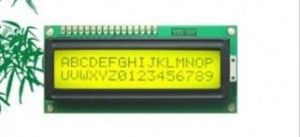
16×2 character LCD module
10k ohm potentiometer
a breadboard and a bundle of jumper wires
We could build it step by step if you have no previous experience of using DHT11 sensor and 16×2 LCD display module.

First of all, we shall take a in-depth look at DHT11 temperature and humidity sensor. This sensor includes a humidity measurement component and an NTC temperature measurement component, and connects to a high-performance 8-bit microcontroller.DHT11′s power supply is 3-5.5V DC.
The interesting thing in this module is the protocol that uses to transfer data between MCU and DHT11 sensor. All the sensor readings are sent by using a single wire bus which reduces the cost and extends the distance. One communication process is about 4ms.Data consists of decimal and integral parts. A complete data transmission is 40bit, and the sensor sends higher data bit first.
Data format:
8bit integral RH data + 8bit decimal RH data
+ 8bit integral T data + 8bit decimal T data
+ 8bit check sum.
More details related to DH11 sensor module please visit our Wiki.
Because of the original code to read DHT11 sensor module is so “obscure”, we can import a DHT sensor library to make it work more obvious and more user-friendly. You can download DHT library here, then drag the DHT folder into Arduino/libraries/ folder and restart IDE.It’s fairly easy to connect up DHT11 module to Arduino, pin S is for data output.
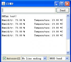
Now load up Examples-DHT-DHTtester sketch. Since the DHT sensor library is not only for DHT11 sensor module, but also for other types of DHT sensor, such as DHT12,DHT22. Therefore, the code need to change a bit for fitting your sensor module, or else, it doesn’t work properly.

In following step we need a 16×2 character LCD module that IC controller is HD44780 or compatible, these is usually be the common found in retail stores. There are many ways to interface this LCD to Arduino board,4-bit, 8-bit parallel and so on. Here we choose the easiest method 4-bit parallel interface.

There are 16 pins on the LCD module, pin label details please visit our wiki. The pin labels of different type may have a little change, but in general it’s almost the same. Now we can connect 16×2 LCD screen to Arduino board using the diagram below.
The 10k ohm potentiometer should be connected to pin3 for adjusting the display contrast.Likewise, for convenience, we could use the LiquidCrystal library which should pre-installed in the Arduino IDE. We can load up the Examples-LiquidCrystal-Helloworld to inspect if the Lcd sreeen is working normally.
What we do on next step is more easier, just connect the DHT11 sensor module to Arduino board.Schematic is following.


Current temperature and humidity in Shenzhen, China.
Code: Select all
#include “DHT.h”
#include <LiquidCrystal.h>
#define DHTPIN 8
#define DHTTYPE DHT11
DHT dht(DHTPIN, DHTTYPE);
LiquidCrystal lcd(12, 11, 5, 4, 3, 2);
void setup() {
 Serial.begin(9600);
 lcd.begin(16, 2);
 dht.begin();
}
void loop() {
 float h = dht.readHumidity();
 float t = dht.readTemperature();
 if (isnan(t) || isnan(h)) {
   Serial.println(“Failed to read from DHT”);
   }
 else {
   lcd.setCursor(0,0);
   lcd.print(“Temp=”);
   lcd.print(t);
   lcd.print(” *C”);
   lcd.setCursor(0,1);
   lcd.print(“Humidity=”);
   lcd.print(h);
   lcd.print(“% “);
   delay(500);
 }
}
