Page 1 of 2
GT2560 and 5V servo
Posted: Wed Sep 09, 2015 9:51 pm
by micheleamerica
Hi forum members
I've just bought a GT2560 controller board and would like to include, in my 3d printer, a servo controlled bed leveling jig but I do not see how I can connect and control a servo with this board.
Can anyone please elucidate if it is at all possible ? And if so how can it be done ?
Thanks in advance.
Re: GT2560 and 5V servo
Posted: Fri Sep 11, 2015 9:02 pm
by Mark
Re: GT2560 and 5V servo
Posted: Fri Sep 11, 2015 9:21 pm
by micheleamerica
Thanks for the link.
I'd already checked it and saw nothing concerning the connection of a servo to the GT2560.
Does that mean that there is no possibility to do so ?
Re: GT2560 and 5V servo
Posted: Sat Sep 12, 2015 1:10 pm
by KrzyInuYasha
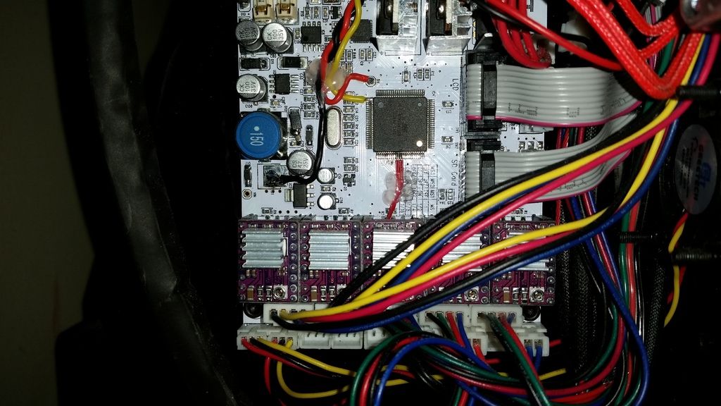
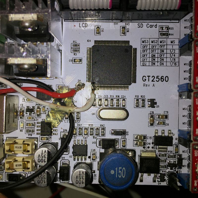
There is no easy way to wire a servo up to this board since you have to directly solder onto it, I've done it on mine (though still need to test) and the hardest part is the signal wire. As you can see in the photo below the Ground and 5v supply is easy enough, the hard part is the signal wire either has to be soldered directly to the pin like I did or you can solder it onto the pad of R22 that faces the main chip. I basically was following the wiring and set up for the Ultimaker board, so if you need more info i would search for that if you need more info.
P.S. ignore the 4 small red wires soldered to the chip next to each other, those are for a bluetooth serial mod i did.

Re: GT2560 and 5V servo
Posted: Sat Sep 12, 2015 8:42 pm
by Mark
A huge project...and the manual welding technique is perfect!
Re: GT2560 and 5V servo
Posted: Tue Nov 10, 2015 11:50 pm
by eibsen
KrzyInuYasha wrote:There is no easy way to wire a servo up to this board since you have to directly solder onto it, I've done it on mine (though still need to test) and the hardest part is the signal wire. As you can see in the photo below the Ground and 5v supply is easy enough, the hard part is the signal wire either has to be soldered directly to the pin like I did or you can solder it onto the pad of R22 that faces the main chip. I basically was following the wiring and set up for the Ultimaker board, so if you need more info i would search for that if you need more info.
P.S. ignore the 4 small red wires soldered to the chip next to each other, those are for a bluetooth serial mod i did.
Have you tested this mod? I am very interested to mod mine for a servo as well.
Re: GT2560 and 5V servo
Posted: Wed Nov 11, 2015 8:12 pm
by KrzyInuYasha
No, I've been too busy to dive into the code and test things and see what is needed for it to work. I really haven't touched my printer since changing the head carriage for the auto level mod and wiring the servo up. Not sure when I'll get the chance to do so either, all I can say it look into Ultimaker auto level mods and code that use Pin 13 of the Ultimaker board since this is based off those mods.
Re: GT2560 and 5V servo
Posted: Mon Nov 16, 2015 9:23 pm
by eibsen
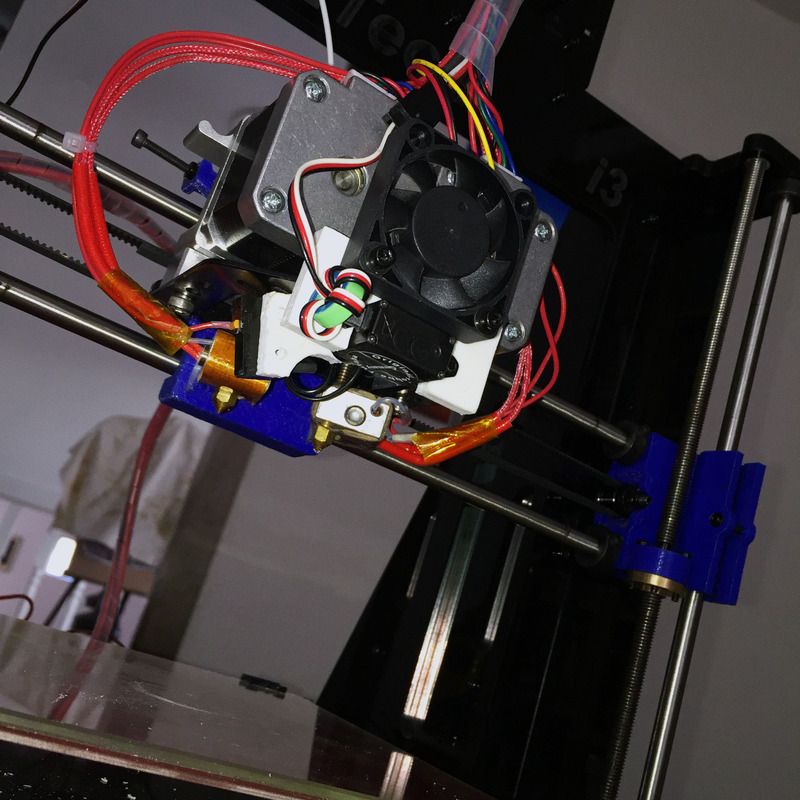
Since my smooth rods for the X-axis are bent (bad quality from Geeetech) and it is almost impossible to fix them, causing very inconsistent prints I decided to go ahead with the mod for the Auto Bed Leveling. It went very well I must say. The soldering was difficult and looks like a mess but I managed to complete it. I decided to tap the NULL (GND) from the other side of the board. I designed a bracket and a probe arm for the Geeetech Prusa I3 pro C. The only problem I got was when I was compiling the FW in Arduino 1.6.5 I kept getting this error message:
------------------------------------------------------------------------------
Build options changed, rebuilding all
temperature.cpp: In function 'void manage_heater()':
temperature.cpp:665: error: unable to find a register to spill in class 'POINTER_REGS'
}
^
temperature.cpp:665: error: this is the insn:
(insn 98 97 100 4 (set (reg/v:SF 103 [ pid_input ])
(mem:SF (post_inc:HI (reg:HI 146 [ ivtmp.209 ])) [4 MEM[base: _110, offset: 0B]+0 S4 A8])) temperature.cpp:449 99 {*movsf}
(expr_list:REG_INC (reg:HI 146 [ ivtmp.209 ])
(nil)))
temperature.cpp:665: confused by earlier errors, bailing out
unable to find a register to spill in class 'POINTER_REGS'
------------------------------------------------------------------------------
I soon figured out that it was a compiling error and switched to Arduino 1.0.6 and then everything worked brilliantly.


Re: GT2560 and 5V servo
Posted: Sun Jan 03, 2016 8:41 pm
by gidim
Hi Eibsen.
Can you please share the Marlin code that you have used for the auto level to run your board?
What changes did you make to use PB7 as your PWM for the servo?
Thanks.
Re: GT2560 and 5V servo
Posted: Mon Nov 21, 2016 7:03 pm
by 3DSarge
Thanks for posting this, I have been able to do this mod and get the servo working. I can't believe the board designers didn't think to open a few auxilliary pin headers for expansions like servo control. My board version doesn't even have 3-pin endstop ports, only 2-pin! (there is another method of servo connection that supposedly works via a 3-pin Z endstop port)
Regarding related changes to the Marlin firmware, SERVO0_PIN needs to be set to 13, not 7, as PB7 is on Port B. Not sure how it turns out to be pin 13 as it should logically be on 15

Regardless of confusion, 13 works for me. Needs to be set in pins.h, under the motherboard 7 section (or just change all assignments to SERVO0 to 13 in this file to be sure)
I also found that M280 command wasn't working; I think this was due to PROBE_SERVO_DEACTIVATION_DELAY being commented out, i.e. "undefined", so you may want to activate that in configuration.h


