Hello,
I've ordered 2 Geeetech Prusa I3 pro B in november.
I begin to assemble one of them for a gift at christmas.
It has work prettry good, I reuploaded the firmware for wrong X axis way and only a feeding problem on the extruder that was about to be settled.
But since 2 days, the printer don't start, no lcd, no fan, just the green led on the control board.
Also nothing when I plug it to my computer (nothing appends, no yellow led).
I tried to change the control board by the second one, same problem (defective too ? this one works on usb)
tried to change the power supply same problem.
I think my 2 control boards are defective.
What can i do ?
Thanks for your help.
Control Board defective ?
Re: Control Board defective ?
I'm back with the measurement you ask me to do !
For the first i3 proB printer:
the PSU give:
12.18V on V1/COM ------- 12.18V on V2/COM


On the Control Board:
Green led is on.
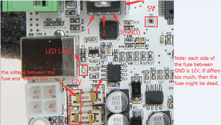
15A FUSE/GND:
Fuse terminal (1): 12.17V -------- Fuse terminal (2): 12.17V


10A FUSE/GND: (this one seems dead)
Fuse terminal (1): 12.17V -------- Fuse terminal (2): 0.0V


Meanchip Power/GND: (must be 5V, for my control board nothing)
Power: 0.1V

For my second I3 ProB: (not assembled)
the PSU give:
11.96V on V1/COM ------- 11.96V on V2/COM


On the Control Board:
Green led is on.
15A FUSE/GND:
Fuse terminal (1): 11.96V -------- Fuse terminal (2): 11.96V


10A FUSE/GND: (seems to be dead too)
Fuse terminal (1): 12.17V -------- Fuse terminal (2): 0.0V


Meanchip Power/GND: (must be 5V, nothing here again)
Power: 0.11V

Now I have questions:
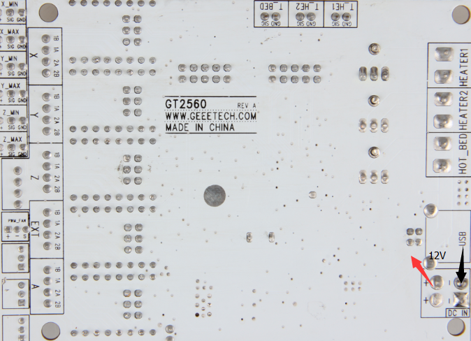
Why are the positive terminals welded on my control boards and not on your exemple?
yours: -------------------------------------------------------------------------- Mines:


Why the fuses on my 2 boards are 15A and 10A and on your example 15A and 5A?
yours: -------------------------------------------------------------------------- Mines:


So what can I do now ?
Thanks.
For the first i3 proB printer:
the PSU give:
12.18V on V1/COM ------- 12.18V on V2/COM


On the Control Board:
Green led is on.
15A FUSE/GND:
Fuse terminal (1): 12.17V -------- Fuse terminal (2): 12.17V


10A FUSE/GND: (this one seems dead)
Fuse terminal (1): 12.17V -------- Fuse terminal (2): 0.0V


Meanchip Power/GND: (must be 5V, for my control board nothing)
Power: 0.1V

For my second I3 ProB: (not assembled)
the PSU give:
11.96V on V1/COM ------- 11.96V on V2/COM


On the Control Board:
Green led is on.
15A FUSE/GND:
Fuse terminal (1): 11.96V -------- Fuse terminal (2): 11.96V


10A FUSE/GND: (seems to be dead too)
Fuse terminal (1): 12.17V -------- Fuse terminal (2): 0.0V


Meanchip Power/GND: (must be 5V, nothing here again)
Power: 0.11V

Now I have questions:
Why are the positive terminals welded on my control boards and not on your exemple?
yours: -------------------------------------------------------------------------- Mines:

Why the fuses on my 2 boards are 15A and 10A and on your example 15A and 5A?
yours: -------------------------------------------------------------------------- Mines:

So what can I do now ?
Thanks.
Re: Control Board defective ?
https://www.geeetech.com/forum/viewtopi ... 18&t=18734
i asked a similar question and got this response.
"Why are the positive terminals welded on my control boards and not on your example?"
its intentional, not a defect; i imagine it might be for a greater current source or something, the finer details evade me.
i asked a similar question and got this response.
"Why are the positive terminals welded on my control boards and not on your example?"
its intentional, not a defect; i imagine it might be for a greater current source or something, the finer details evade me.
